Showing posts with label Assignment 2. Show all posts

Monday, February 13, 2017

Brandon Wehenkel: Prosthetic


 Mechanical Horse Leg Front


Mechanical Horse Leg Left


Concept:
Anthropomorphism is, by all means, my most favorite form of art.  It's one of the oldest variations of sculptural form discovered.   Egypt was where it began for me.  Their culture was by far the most anthropomorphic cultures in history, they have a god/goddess for everything, and many are half-man-half-animal.
In my brainstorming phase, I remembered seeing an elephant that received a prosthetic foot.  Think about it, that prosthesis has had to have been a super strong material to withstand the weight of an elephant.  But as I always try to make everything 50x harder than it has to be, I thought of my friend and his love for horses.  I wanted to design a mechanical horse leg prosthetic.  It started out as just a regular horse prosthetic but thought about the complexity of horse movement.  Horses require a very complex anatomy to be able to run as fast as they do, so why not make a prosthesis that can also withstand the weight and complexity of a horse stride?  I used Andrew Chase - Mechanical Horse for the project.

I'm not an expert in mechanics but I did spend a lot of time, about 4 years, learning the mechanical make up of a weapon while I was on board a navy ship.  The Gyroscope (not actual mechanism, but similar) and the wobble gear (not actual mechanism, but similar) were one of the most complex mechanical mechanisms that I did maintenance on.  I really didn't enjoy the maintenance but I did love the complexity of the mechanics.

Also thanks to the excellent Ted talk by Aimee Mullins for giving me the idea.  I very much enjoyed seeing her anthropomorphic body morph where she portrayed a Cheetah with actual Cheetah hind legs as prosthetics.  She can be seen in "Cremaster 3," (2002) a film by © Matthew Barney.


 Ghosted Black


Organization Colored


Modeling Techniques:
About 80% of my design is copied from Andrew Chase's design, but I didn't make everything as crude as his design.  He made it look like actual welded pieces of sheet metal. I really liked the natural angles of a horse and morphed the angles of the knee and the hoof to match a horse's actual resting position.  So what I did was look up Horse anatomy by Herman Dittrich and drew some photos that resembled muscular anatomy.  I mostly just traced his designs so I could get correct angles.


Anatomical referenced leg


The image above was the leg I had based my mechanical drawing off of.  I used curve interpolate points to create the outline of my reference image from both the front and right sides.  I then manually bent the front curve to roughly get as center as possible from the right reference curve I created.  I used F10 to get the control points for the curve. The reason I bent the front curve was so I could create inner circles to loft the shape.  I used 103 curves to create the mesh for the form.  I lofted all of those curves together, which I give great thanks to Professor Scott for the assistance, and that is the image you see above.  The only difference is the green hoof is different.  I used that hoof and adapted it for the mechanical parts.  It's not entirely mechanical looking, but I think it looks better than the hoof in Andrew Chase's model.  I was not getting the NetworkSRF to work, so loft did the same thing for me.


Keyshot - Left and Front angles with Reference Images


Keyshot - Right Angle


From here on out it was very easy for me, organic stuff just doesn't click well yet.  I used MoveUVN coupled with Select U and Select V to smooth out all of my yucky curves.  Something that saved me hours, unlike my stupid mouse.  Thanks again Professor Scott for giving me this incredible tool.  It's the most essential tool for this project.


Keyshot - Gear / Knee


I used pipe for the cylindrical sections of the shin and thigh.  I created a cylinder for the knee gear, ankle, and a couple other locations on the top basket.  The knee is the only gear with slots on the leg.  I created the cylinder, a small box, and used array polar with 180 degrees to make the gear.  I used the reference image to create a majority of the shapes with curves and then extruded them.  The nub box on the top was purely impulsive.  I wasn't sure how I was going to draw that in my references so I left it out to sculpt later.  This was the hardest part for me to design because I wasn't sure what to do.  I used boolean difference to create the spot where the nub of the leg will rest inside.


Keyshot - Nub Seat and Ball Bearing Gear


Materials:
I wanted to use a tough metal like Titanium or Steel, but their color spectrium wasn't working for me even when manipulating the attributes.  I really liked Zinc's attributes because it had more than one color slot.  Then I used the pearlescent metals because they have the flakes.  I really like seeing pearlescent paint on cars.
Color inspiration, I used zinc and recolored it to more resemble the fire-bronzed metal on the image, I used colored metallic paint similar to the fingers.  And I wanted to add a little touch of color so I used another colored metallic paint and used one of the browns for the nub seat.  I changed the color of the flakes to make the overall color brighter and somewhat match the orange sheen similar to the other metallic paint I used..


Keyshot - Hoof and Ankle Detail


Friday, September 9, 2016

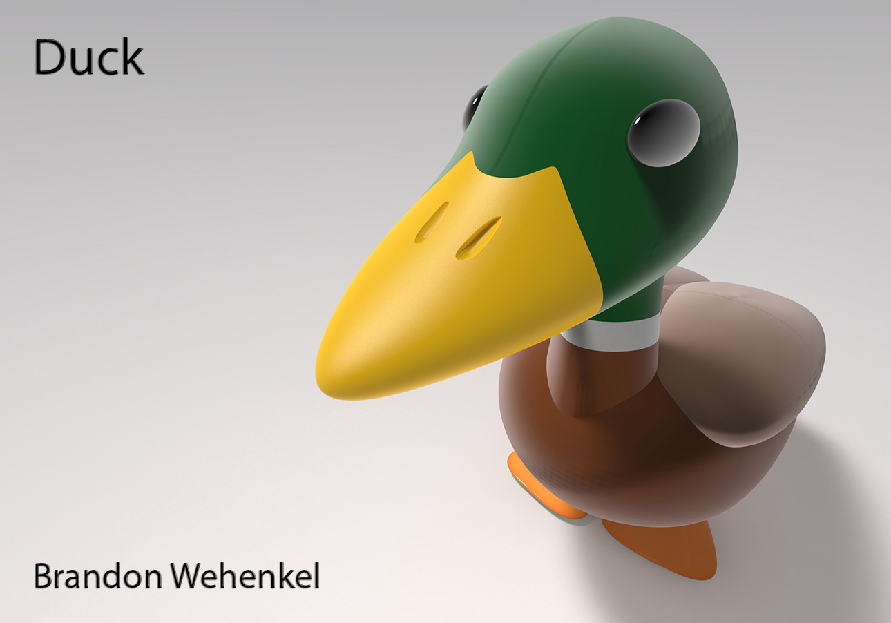
Brandon Wehenkel: Duck


 Black & White Ghosted

Colored Ghosted

Concept:
I googled "Duck" and saw a Mallard duck and thought it was the cutest variant of duck that I could find.  I liked their distinct green head.  I don't see ducks very often and I noticed a lot of the submissions were of rubber ducks, so I felt that making a more natural duck would be interesting.


Modeling Techniques:
I followed the tutorial to the teeth.  This was my first organic model EVER and it was quite up there on the difficulty scale for me. Just like the tutorial guided, use Edit --> Rebuild, to create more geometry in the sphere to work with.  Press F10 to get more vertex points to manipulate in to workable shapes. Use Transform --> Set XYZ Coordinates to manipulate points according to set coordinates.  Use Polyline tool to Project new curves onto surfaces.  Use Trim tool to cut out holes. Use Blend Surface to create the neck.  Repeat steps for new geometry.  I used Boolean Difference to create the wings and the nostrils, and Boolean Union for the flippers.
When designing the duck I had noticed that the body shape and the neck were different than what the tutorial had described so that's where I broke off.  I added the wings to add more detail, and the flippers to balance the body.  I also skewed one of the feet to hopefully aid in the stabilization.


Materials:
I liked what the Velvet material did to imitate the sheen of the feathers on the birds head.  So I added that material on everything except the flippers, the eyes, and the beak.  The beak and the flippers have a hard plastic material.  The eyes are a translucent metal with black as the diffuse.


Problems:
  1. I was not sure how to create closed polysurfaces once I used the polyline tool to dissect and trim the shapes. The best example was the beak to the head, the complex line that I drew to create the curve could not close to make a closed shape.  I was using Cap Planar Holes and Extract Surface but they weren't working.  In the initial photo when displaying that I had zero naked edges, I had combined the head and the beak as well as the few parts of the neck together so that I had closed poly surfaces.  Then once I took the photo I separated them to take into Keyshot, where I had a couple errors.  I fixed the errors by re-opening the program till there wasn't any texture bleeding, that way I could separately materialize each part the way I intended.
  2. I had more than one seam ending in the textures on multiple surfaces.  I was unsure how to fix them.

Sunday, March 1, 2015

Renae Patoskie Week 4: Flashlight Sleeve

I wanted my flashlight sleeve to be about practicality and ownership. After experimenting with the different capabilities of Rhino, I decided not to have any extrusions on my final model. A flashlight of this size I would use a keychain, in which case it will be handled roughly and without consideration, therefore my design does not have any parts which could break off. I wanted to guarantee that the flashlight and sleeve could not be easily separated so I added an interior lip to contain the flashlight and added a screw feature so that the two halves would hold the flashlight inside. Finally to maintain the practicality of the flashlight, a hole was left in the base of the sleeve to grant access to the on/off button.

Ghosted view with no naked edges.

Layer organization.

In this model I used an outline and revolved the basic shape; created the screw feature, using spiral curves, the flow along curve function, boolean union and boolean difference; added the Light and Renae extrusions by projecting UV curves, adding text and then removing the volume of the text using boolean difference.


View 1 of Keyshot Rendered Model. 

View 2 of Keyshot Rendered Model.

Final printed model.

Sunday, October 12, 2014

Christopher Chambers - Project 2: Flashlight

I was going more for lightsaber and fell short at screwdriver, but it works!


(image courtesy of Wookiepedia)


Shall render when we figure Keyshot here in class today.


---

"The Business."


 It gets the job done.

---


Not too shabby, either. Wound up printing this one myself, however, with some ~20 hours of learning experience. Calibrating printers is troublesome!

---


Functional!

Christopher Chambers - Project 1: Submarine

First time touching Maya in 5 years or so, making for quite an experience! Wound up working with polygons as creating what I'd planned to in NURBs proved to be immensely difficult.


For a while I've been wanting to make little 'plug-together' miniatures for 3D printing, opted to go with a submarine for the first try. A lot've influence came from both Total Annihilation and Planetary Annihilation, as their silhouetting-based style is pretty neat. Started with a shape and went from there, mostly via extrusion, until it looked roughly like what I'd had in my head. It's a water-jet based boat, hence the lack of fins! The bits hanging off of the sides are supposed to be a cover for the open bay.

Some references:


Update!

Ran the Shapeways checks and it seems there's a single spot on the model that wound up giving a 'Thin Walls' notification, due to a portion that tapers, as seen here:


I had, interestingly, also found that Shapeways has a lot easier a time running checks for non-plastics than plastics (or at least displaying them), as seen here:

Plastics -

Metals -

I believe I've fixed the problem but I need to double-check the scaling in Rhino whenever I next find myself on campus.

-----

UPDATE BELOW THIS POINT

-----

As it turns, the model I'd initially uploaded did pass for most of the plastics!


As in the previous update, the 'thin walls' section just wasn't loading properly, as they were apparently doing server work at the time.


I also wound up ordering it, as at present my Solidoodle 2 needs quite a bit of work to get into running order again, and I figured it best not to risk something else breaking in the interim!

---


Modified from the original mesh.


The printed version will not be as cleanly lined, but I build models as a hobby so have plenty of tools to fix such. Files ahoy!

---


Polished white, courtesy of Shapeways.

Sunday, September 21, 2014

Andrew Kelly: Project 2: Flashlight Sleeve

Following are two views of my finished project, and the verification from shapeways:

Perspective view showing the front of the model
 Perspective view showing the back/side of the model

----------------------------------------------------------------------------
Week one progress
Here's my flashlight sleeve. I'm still getting a hang of rhino, experimenting with the different tools without any concrete final idea in mind. Input appreciated!
----------------------------------------------------------------------------
Thematic description
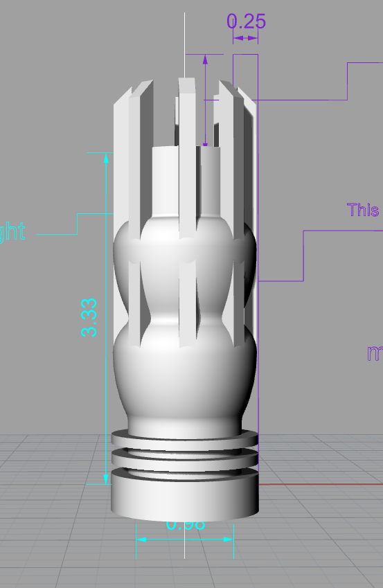
For this project I decided to see if I could carry elements of my previous project over to rhino, as a test of sorts for myself. I also wanted a flashlight sleeve that would be more of a light fixture than a portable utility, so I wasn't worried about comfort in hand or pocket, but I definitely wanted to be able to set the object on the table, turn it on, and be able to enjoy the shadow patterns. The pulsing center stock of the sleeve is a similar profile to the pulse on the loops of my first project, and the rods protruding from the top will hopefully cast strong shadows, so as to be visible even when the light is far from walls  or other objects. 
----------------------------------------------------------------------------
Two Rendered Views of each Model

----------------------------------------------------------------------------
Modeling Techniques
     For this project I utilized surface-based curve-modeling techniques in Rhino, using revolve, loft, sweep, booleans (union/subtraction) and lattice-deformers to make a pleasing model out of simple primitives.
----------------------------------------------------------------------------
Color-Coded Model

----------------------------------------------------------------------------
**Timing failure alert**
Look at those wonderful fluctuating expected/actual delivery dates. 

----------------------------------------------------------------------------
It arrived!