Art of designing an structure is commendable. It takes months to execute the perfection of the structure. I decided to construct the lamp structure by using a solid object. In this case I used an Pyramid shape. I thought this shape would do justice to the design.
Pyramid shape turned out well because the radial contours complemented it. I started constructing the lamp by using a solid object. Once the base was created, I used the contour command, created new layers to make my workflow a little easier, and used the curve intersection command to make vertical and radial pipes.
I used a wood material for my final rendering as the structure required it due to how its designed. I wanted to use red and green color for my lamp structure because these colors complemented the design of the lamp structure.
Experimenting with laser cuts, we continued to develop new techniques within the realm of laser cutting. For this week, we were instructed to create a unique geometric shape in rhino, and have it laser cut out in serial slices, and then glue them together to form the object.
This to me felt similar to the waffle project, only a stepping-stone between the two. I designed the shape, and using add and subtract with other uniquely created (and unused) shapes, I chipped away parts of the model until I was left with a shape I felt was unique in and of itself.
Getting acquainted with the paper folding software, and the wide variety of shapes you can create using the software Pepakura, I designed and created a geometric box, which I then proceeded to fold and glue together to get a nice cube shape.
For our final semester project, we were given the freedom to create an object using the Pepakura unfolding software. I decided to continue my theme of NBA, and wanted to do a replica of the Larry O'Brien NBA Championship trophy.
In real life, the trophy stands a good 2 1/2 feet tall, with a regular size basketball at the top of the trophy. The cone is meant to resemble a net, and together it is a ball going into a net.
I started more detailed, but decided to keep it more simple to make it easier to transfer into Pepakura and layout. I began by modeling the 3 main shapes- a sphere, a truncated cone, and a rectangular box for the base.
While the trophy is already a good size, I wanted to enlarge it, as I feel enlarged objects are more fun and would be a way to tweak the style of the project. Although a little confusion with the scale took place converting between pepakura and Rhino, I found the scaling options within Rhino and decided to make it about 4 feet tall (and some change).
Overall, the project was a lot of fun, and I enjoyed learning the different construction style of Pepakura, which I had never heard about before this assignment.
For our pepakura project, we decided to go with the chess theme and created a rook piece. Zach created this piece in Maya and wanted it to look like a strong model as the rook is portrayed as a castle tower. After finalizing the piece in Maya, we unwrapped it in pepakura designer and brought the unwrapped piece into Rhino to create the fold lines using Grasshopper.
We didn't realize until after the piece was printed that we made the model more difficult to assemble because we unwrapped most of the pieces vertically rather than radially. However, despite this oversight, assembly was fairly straightforward. We attached the sides of the body first, then added the base, put together the top, and finally added the top to the main structure. There are a couple imperfections along some of the folds, but the piece is structurally sound and any imperfections could easily be hidden by tape and paint. Overall, we were both extremely pleased with how this project turned out.
Instead of a chess piece, I actually used an altered model I created for my capstone project: a playing piece for a fictitious board game. The design of the playing piece would be an image of a snake that had been whittled away from a piece of stone, and hopefully the design shows that subtractive sculpting.
Sheet Layouts
Keyshot render 1. I used a normal map I created for my capstone as a test.
Keyshot render 2
Unfortunately a lot went wrong between the print out and me putting it together, most especially my use of tape instead of glue to put it all together.
For this semester, I designed and fabricated a series of four Archetectonic Lamps, experimenting with different aesthetics, materials, and orientations. I utilized the lamp created at the end of last semester to serve as a prototype and starting point for creating this series. Initially, each light piece stood on its own. However, through the evolutionary process of creation, each piece ended up serving as a study in meditation.
prototype from previous semester
Research and Inspiration:
A collection of photos of light fixtures with compositions I was drawn to, and which I thought might translate well into modular compositions, can be found in this Flickr album. I then created rough sketches of about half a dozen different types of lamps, and met with Dr. Scott to discuss work processes, as well as what alternative materials and light fixtures might be available. I underestimated how beautiful some light bulbs can be, and found new materials with which I had not previously worked.
Serial Lotus:
Wall mount, gray- stained birch wood and bronze cast acrylic
I've wanted to work with plexiglass and light after seeing Dr. Scott's example last semester. I wanted to create a light piece that felt serene but also commanded attention. I thought it would be fun, visually, to layer wood and plexiglass in order to create an overall impression of a lotus flower with light emanating from the inside. For this, I utilized the serial slicing method, and built a box that ran through the mid layer to hold the light source. To create the lotus shapes, I made paths from different inspiration source images in Adobe Illustrator, then imported the paths into Rhino as curves. This design technique was taught to us during the Pepakura and Origami projects, though the physical build is set up like a serial slice. The cardboard prototype for this piece was very useful in designing the negative space that was needed to accommodate the light fixture in the mid panel.
^ scale image ^
Chandy:
Hanging, textured paint on hardboard with Shoji paper
The idea with this was to create a flourished silhouette of a chandelier as a radial rib and seat them around a small diameter cylinder. However, I could not hit this concept right on the scale that I wanted, so I designed decorative panels in lieu of the silhouettes. Again, I used Illustrator to create the fan shape and inner design, then imported it into Rhino. Once in Rhino, I was able to smooth out the rough paths of Illustrator's pen tool and rotate duplicates around a center column.
The prototype was where I made manual edits that I then carried over into the digital design. Some grillage was removed, the inner design was simplified, and a decision was made to sandwich Shoji paper (really pressed fiberglass) between the fan planes and give each plane more visual weight by doubling up the material.
I dearly wanted to make a softer light for a kitchen space, so I decided to play on the idea of a dinner bell. The overall shape had to be created in Maya, and once imported into Rhino the interior was Boolean differenced out. The original bulb for this piece was discarded once the cardboard prototype was assembled, along with some original grillage. To edit those manual changes digitally, I simply deleted the unneeded ribs and mended the notches with Boolean curves. I also adjusted the fixture openings to fit a standard socket, in lieu of the prototyped chandelier socket.
The Shoji paper interior was the result of design evolution and playing around with the prototype. The end result is a bit too nice for my kitchen, but it does transition well to an outdoor piece.
Nest:
Blue stain on birch wood with stainless steel wire
On its initial creation, this piece was going to stand very tall and have smooth lines that exaggerated the natural line of a forearm. The shaped was modeled in Maya by manipulating a cylinder and edge rotation. Once imported into Rhino, the light space was hollowed out and the model was again resized.
However, after handling the cardboard prototype, I felt it best to truncate the piece and play with the inner negative space as the concave part of a bird's nest. The lines on the truncated piece had a sci-fi look to them, and played well when the small globe light was placed inside, mimicking an egg. This globe light was originally meant for the Bell piece, but the prototypes allowed me the chance to preview possible extreme design changes. The nicest thing about this prototype process - the final layout design fits perfectly in a 24"x24" area, so I can cut 2 on every 2x4' sheet :)
^ scale image ^
Best lesson learned: cardboard prototypes were the best tools I had this semester!
'The prototype was where I made manual edits that I then carried over into the digital design.'
We decided to start by each modeling our own design,
ultimately choosing the one based on the below reference image. The design,
modeled by Michael, was an attempt to have a clear Knight model, while
retaining a polygonal and minimalistic style. The end result turned out very
well and close to the reference.
The model was made in Maya, starting with a cube. The cube
was extruded multiple times to create the main body all the way up to the head.
The head was created with a separate cube and extruded back to the neck. The
main was made from the back of the neck, extruded back and enlarged. The ears
were from extracted surfaces on top of the head. To create the final project,
the model was made and unfolded by Michael, and then formatted and layed out in
pepakura by Austin. It was then converted to rhino and formatted using
grasshopper for cutting. Both members then worked on the cardboard final to put
it together.
For this project, we wanted to create a simple, polygonal piece that was easily recognizable as a queen. We used renaissance era hats as inspiration, and create the head based on that shape. The base of the model is an octagon, signifying the 8 ways a queen can move across the chess board.
Modeling was done by starting with an octagonal polygon, then extruding it upwards and adjusting the faces until the desired shape was completed. Attaching the top piece to the rest was difficult, as the base was a square. In the end, we used the 4-point planar create tool to create the desired surface, then joining the pieces together.
As with my lamp post, I forgot that I wouldn't be able to get the needed pictures of the modeling process without Rhino, so I only have a picture of the finished project. I apologize for this lack of forethought.
For my lamp project I went through several design ideas, eventually settling on one derived from my flashlight model from the first project. The model was scaled in two dimensions and tapered slightly to give it a new shape with a wider interior that would lend itself better to fitting a hand to change a bulb. when adding the contours to modify the model I wanted to emphasize the ridged pattern on the bottom, so I applied more vertical contours on the lower half. I also wanted to have an open front, which led to some problems on the printed prototype in conjuncture with slightly too small slots that made it difficult to assemble the model correctly. I also missed the flat base when unrolling the planes, necessitating some modification on the prototype to allow it to stand. Future iterations of the project would have the radial planes moved forward to better balance the structure.
Developing the Idea: In my second semester for this course, I set out with a fairly ambitious goal - to design and build a pendulum clock or other gear-driven kinetic sculpture. Clocks:
(image via wikimedia commons)
Clockwork art has a long and storied history, starting with the invention of of the first escapement gears as early as the 1050s in China. An escapement is the mechanism which allows a power source - water, springs, motors, etc - to be divided into discrete units of motion in time. This is the tell-tale tick-tock of a pendulum clock, which was the absolute pinnacle of timekeeping technology for two centuries. A power source becomes motion becomes our measurement of time -- a fascinating idea with a lot of potential for artistic exploration.
Through gear trains, the speed of motion can be sped up or slowed down for different timescales, and adding additional power allows for chimes or animated figures -- this is why most grandfather clocks have more than one weight. One drives the gear train, and the other drives the chimes -- a third might power just the midnight chimes.
By the way, the pendulum only supplies timekeeping, not power. The gears are turned by the weights alone. Today, making pendulum clocks tends to be the niche of ambitious woodworkers, but they’re definitely cool. Here are a few by Clayton Boyer, who sells schematics of his clocks on his website:
clocks by Clayton Boyer
clocks by Clayton Boyer
Pendulum clocks require a lot of precision-cut, flat pieces. Sounds like the perfect task to apply to a laser cutter.
Kinetic Sculptures Ultimately, the complexity and precision involved with making a clock (combined with a pretty nasty workload this semester) has caused me to put these designs on the shelf for later. Instead, I’ve decided to focus on a much simpler, manually-driven kinetic sculpture. Artistic, sculptural clocks are one small subset of a larger category -- kinetic art. In its most basic definition, kinetic art is art that moves. Like clocks, that motion can be driven by a variety of power sources, like wind in many Anthony Howe pieces:
Or, with electric motors, like those by Bob Potts:
In my research on clocks, though, I stumbled onto the work of David C. Roy, who does beautiful spring-powered kinetic wall art.
One piece in particular really caught my attention:
The concept is so simple, but so aesthetically pleasing, that I knew I had to try a version of it myself.
Breaking Down the Problem
My first task was to make several key decisions:
how do I power the device?
what are the constituent parts necessary to build the piece?
how do I weight the pieces so that they maintain their orientation?
what pieces can I cut on the laser, and what other hardware will I need?
how can I quickly iterate designs in order to find a pleasing pattern?
To help me with these decisions, I have a few personal goals to keep in mind as well (I’ll address whether or not I met these goals a little later on)
simplify - What is the simplest way to achieve this effect? I can add bells and whistles later once a proof-of-concept is done
Integrate off-the-shelf hardware - try not to get bogged down in what is possible with the laser -- there are a lot of problems that can be solved with a trip to the hardware store, even if I didn’t make the parts myself
Iterate - try to develop one idea at a time, and make sure it works before moving on to the next step. Don’t be afraid to make mistakes.
Next, I need to break down the problem. Each piece consists of a number of “orbiters” around a central axis, independently weighted so that they maintain their orientation. Simple enough conceptually!
Iterating in Software
For me, a design challenge like this lends itself to a programmatic approach.
I set to work experimenting with different patterns to try out as orbiters, via Rhino's curve tools and CurveBoolean:
I wrote a Python tool in Maya which takes meshes (exported from Rhino in most cases) and automatically rigs and animates their rotation around a central axis. The tool also had the ability to switch out backplate designs and assign shaders for color testing. Most importantly, I can dynamically assign the number of orbits and "layers" to optimize spacing.
Ultimately, the plan was to make a plug-and-playable system for iterating a wide variety of designs for these types of sculptures, and “prove out” each design before manufacture. Time constraints made this untenable to fully implement, but for the future it would be fun to play with this idea. Unfortunately a laptop crash has completely wiped the tool from existence. Here is a video of the end result -- several interesting patterns, a variable number of orbiters, and different types of layering. The first part of the video is a different concept, which I may return to at some point, when I have more experience with gear-driven designs.
Bearing With Me for a Moment…
My design (and David Roy’s, incidentally) relies on gravity to maintain the orientation of the rotating “orbiters” -- this means I need a free-rotating axis at the center of each one, and a free-rotating axis at the center of the wheel. This means using bearings.
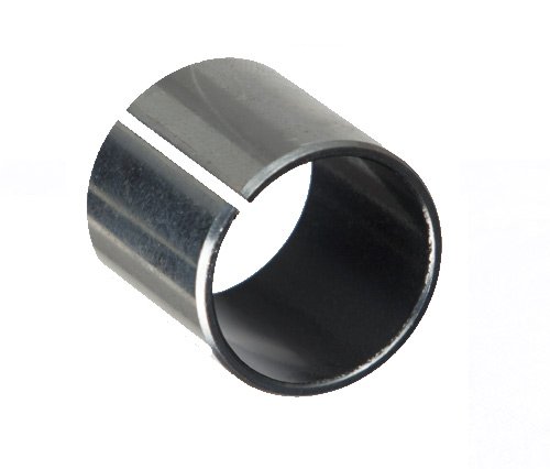
The simplest kind of bearing is just a sleeve that you can put an axle or post through. Not very exciting but effective in most clocks. For my needs, though - I needed a solution which would give the orbiters zero “play”. I did purchase some PFTE sleeve bearings to experiment with, but they were too wide to be useful in this application.
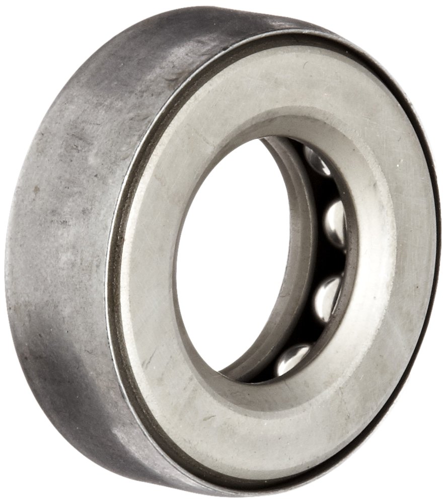
Moving up, you get into two types of ball bearings which might be suitable for my needs - first is a thrust bearing, or “lazy susan” bearing, which is two pieces “sandwiching” metal or nylon balls. These are ostensibly meant for perpendicular loads, like a lazy susan. In practice they could be used horizontally, so long as the weight they hold is small enough
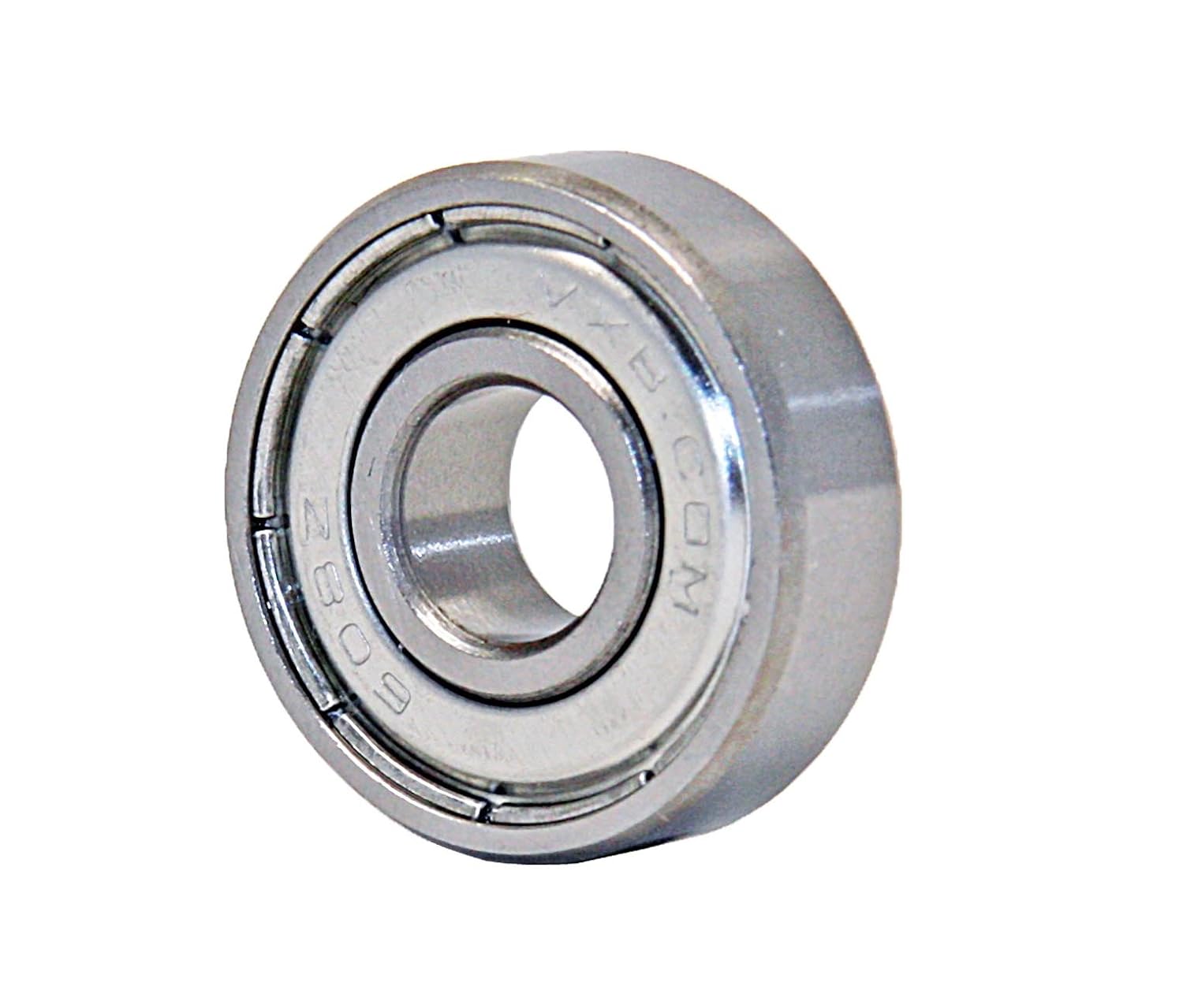
The other type is a radial bearing, or wheel bearing. These bearings are structured so that they hold a radial load, like a wheel, using a layer of balls between the axle and edge.
Both have tradeoffs in terms of functionality:
radial bearings are going to be harder to integrate, but will spin easier in a horizontal position
flush bearings will be easier to build with, but aren’t meant to spin with a radial load
I ended up getting a pack of industrial flush bearings and skateboard wheel bearings to try.
Prototype 1:
Considering the easier construction with the thrust bearings, my first task was to test out their feasibility. I had a flew plexi panels that I wasn’t going to use for this project, so I quickly glued up a mockup to see how they rotated:
Two problems immediately arose - if the plexi got too heavy (three layers of .118 acrylic at around the size I was aiming for) the flush bearings needed a little convincing to rotate well
Problem the second: the bearings come pre-lubricated, and unless you’re very careful about cleaning off all the grease, the glue just peels away a layer of grease rather than sticking to the actual metal of the bearing.
With this in mind, I still thought it was worth the extra ease to attempt using the flush bearings for the first prototype.
these images show the final patterns that the sculpture is meant to oscillate between
the etching lets me quickly line up the pattern layer onto the weighted material, which worked quite well
these small pits allow me to insert a magnet, allowing quick fine-tuning of the weights
Assembly went well, but again I ran into some major problems:
First, I didn’t allow myself enough wiggle room for wobbling. - the heat of the laser has a tendency to warp thin acryclic, and the material isn’t perfectly flat to begin with. My clearances weren’t nearly enough to allow for that warping. Second, the glue on the flush bearings lasted exactly five days. After that, a small tug just tore the pieces apart. Third, the layered-acrylic approach added uneven weight, making maintaining orientation extremely difficult.
In theory, I could add weight in a fine-grained way with my magnets. In practice, the first prototype was too much of a mess to be worth experimenting with. I still like the idea of this modular approach to the problem, though.
Prototypes 2 and 3:
The second prototype was mostly a cannibalizing of the first for parts to experiment with. I came up with two solutions that actually met my earlier goals pretty well:
replace the pattern layer with paint -- it weighs a lot less than a layer of acrylic
use hardware in place of layered-up pieces of acrylic for posts
wheel bearings in place of thrust bearings
Final Build:
using the acrylic masking as a paint mask worked remarkably well
after painting
peeling the remaining acrylic masking
assembly went well until the humidity caused the glue to fail - upon re-gluing many bearings were badly off-axis.
using adjustable hardware made aligning and leveling the posts much easier and more precise
the final assembled product!
Conclusions:
Basically, this project was a very educational failure. The original concept just never coalesced, and there were still a lot of blind spots in my design and construction of the final piece (such as - no way to mount it on a wall yet!)
It almost works. I ended up having to re-glue several of the wheel bearings, and they got mis-aligned. If you look at the final product, you can see a distinct tilt to several of the orbits. Luckily, the new approach to construction allows for a lot more clearance in this case, but it still doesn’t spin correctly. In the end, this was a cool idea that just didn’t quite pan out.
Lessons learned
Start as simple as possible when you’re out of your element - I spent a ton of time early in the semester researching and learning about clocks and clockwork, which ultimately was just too big of a problem for me to take on, given my lack of any real “making” experience, and significant lack of time for experimentation.
if you’re working with expensive materials, mock things up in cardboard or MDF - I could have saved a ton of time and money if I’d been able to test things out without having to use the acrylic. Of course, time was my major consideration, but honestly the first prototype should have been a cardboard mockup to test spacing and clearances.
sometimes, doing things the hard way is the right way - This design really should be gear-driven, with a spring or electric motor. It makes a lot more sense to force the orientation of the orbiters rather than letting gravity do the work. It would be cleaner, more flexible, and ultimately simpler to assemble. There’s a lot more up-front investment in expertise and design, though.
using etching on acrylic to make masking areas is really great - If anything, this was the best takeaway from this whole process, and I plan to make significant use of it in the future. It's like custom paint-by-numbers on plastic. Wonderful!