

Concept:
My focus for Digital Fabrication this semester is the study, design, and fabrication of various prosthetic accessories for specific uses. My first project, which is for a below-knee accessory, will be a prosthetic accessory for scuba diving. I’m calling it Lyretail (or alternately, Scalefin), because my main inspiration for the form comes from a family of gorgeous saltwater fish called Lyretails, also sometimes known as Scalefins. It’s also a fun play on words, and I’ve become endeared to it. There are many variations of the lyretail, but they all have exaggerated and slightly asymmetrical tail fins, and their coloring tends to be dramatic. My goal for this design is to make a diving prosthetic that echoes the streamlined and elegant forms of oceanic fish. The flipper will be similar to a split-fin in that the paddle will not be a solid piece - it will be for diving in conditions where the tide is less strong and unpredictable and you want a little more fine control of your movement. The lower leg portion of my concept draws from the shape of the wings of a manta ray.


From my research, I’ve gathered that a single-axis foot is what most people want from a scuba prosthetic - this way, the foot/fin only moves in one plane and has a predictable path of motion. Another need is ease of attachment and detachment of the flipper to the prosthetic foot, which in most cases is a Sach foot. Given the limited availability of dive prosthetics out there, it’s fair to say that another desire is more customization of the shell to suit your personal style. With these main ideas, I started concepting the Lyretail. When the model is finished, I plan on the ankle joint being a single-axis of my own design. It will ideally be able to lock in 2 or 3 positions, using some sort of manual dial. Additionally, the flipper will either be modeled in a way that means it can be easily slid onto a foot underwater and tightened around the heel, or it will be modeled so that if it were printed in a flexible and water-safe material, it would be simple to slip on the Sach foot and over the heel. The top leg portion will be completely separate from the flipper, but will be connected to the joint and the Sach foot design that fits into the flipper.
In addition to my online research of scuba prosthetics out there currently, I also interviewed a family friend who is a recent amputee and a dive master. We met and talked about how his dive prosthetic works, and how I could go about making my final design effective but still appealing. He agreed with the need for a single-axis rotation in the ankle, and liked the idea of a locking mechanism - he’s actually been designing something similar recently for his own use, since he’s an engineer by trade - and the need for the flipper to be easy and fast to put on and adjust. I learned that I either need to create a leg design that is a completely functional underwater prosthetic that can use a vacuum and pressurization to stay attached, or my design must be purely a surrounding shell that can fit around an existing prosthetic. I haven’t decided which direction I’m going to go with that yet. He emphasized as well something I need to generally keep in mind in this business: every single prosthetic or prosthetic accessory is designed for a particular person, because everyone’s situation is going to be a little different - height, weight, amputation level, etc. I’m going to keep meeting with him when I have questions about ways to make my design more useful, or if I’m uncertain about my design interfering with its overall effectiveness.


Modeling (so far):
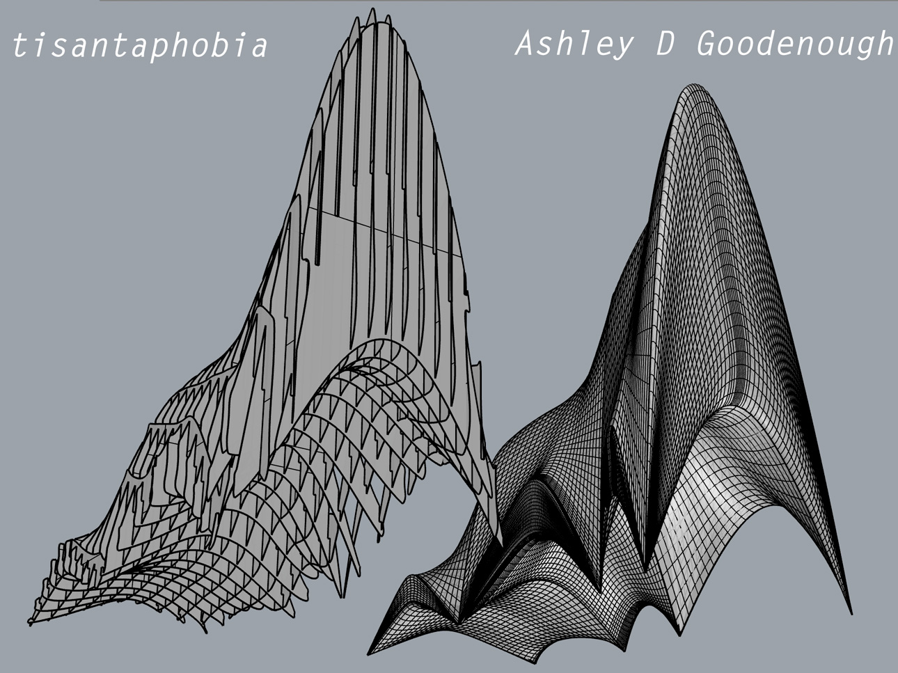
My modeling deliverable at the end of the first four weeks of the semester was to have a clean, preliminary model of my prosthetic last; I would have the main form ready to go, and have very little detail. I got a little further than that, but may have to backpedal after talking with my friend and learning about how his personal diving leg works. I started scaling my concept drawings to each other in Photoshop and setting up some visual guides so that I could bring some orthographic views into Rhino and use them as a reference. I used PictureFrame to set up my front, side, and top views. I used Control Point Curves to first build the side silhouette of the leg and flipper together, then the front silhouette, creating only vertical curves for now. I also used my top view concept of the flipper to curve out the shape of the sole. Then, using Interpolate Points Curves, I drew horizontal curves to basically act as defining curves for the shape of the leg and flipper. I needed quite a few, since the flipper was more complex than a normal foot last would be. I used Rebuild to reduce the complexity of my curves, and made sure I still had intersection where I needed it. Using CurvatureGraph, I tested the continuity of my curves to make sure I was going to build a surface that was relatively smooth with curves that were continuous after I had been splitting and joining them. Before I used NetworkSrf to create my last, I split my vertical curves at the ankle, so that I could have separate surfaces for the leg and flipper, given that the leg could be a much simpler surface if I rebuilt it separately. Then, I selected all my curves and used NetworkSrf to build a loose surface. The flipper turned out to not be incredibly smooth, no matter how much I refined my curves (with RecordHistory turned on), so I turned on control points and sculpted it for a while just by manually moving points around (MoveUVN). I also used SetPt to align my loops to get a smoother surface, and Zebra to test my UV stretching. In the end, I also ended up using ExtractIsocurve to pull some new curves from the surface, and then rebuilt again using those slightly better shapes. Now that I had two surfaces, I could start refining. I used Interpolate Point Curves and Interpolate on Surface Curves to mirror my concept art from the side view, then projected my curves onto the surface. I used Trim to remove the parts of the surface I didn’t need anymore, but kept a copy of the original surface in case I paint myself into a corner later and need it back. Once the top of the flipper and the leg were trimmed, I used OffsetSrf (with Solid checked) on the leg to make it a closed polysurface with a width of a little over 1/8 inch. I FilletEdged every edge to almost the same radius. I attached the pole to the open leg design using some fancy cylinders and DupEdge to mimic my current shapes and a BooleanUnion/Boolean2Objects combination. For the flipper, I used my own foot last design to build an inner hole, then used BlendSrf to connect the two at the top. I used Patch to close up the bottom of the flipper, but had some cross sections to assist it in being smoother. Since that patch wasn’t quite lining up with my flipper and I needed to clothe my naked edges, I used JoinEdge to close the tiny gap.
Materials: Given that the model is not complete and separated into its component pieces yet, I'm holding off on deciding on materials. My favorite idea right now is to mimic the coloring and patterns of the batfish, and use a rubber-like material for the flipper and a hard plastic for the leg (the hard molded part of most prosthetic legs is made of carbon fiber):

References:
https://www.media.mit.edu/videos/ceb-2016-05-06/
http://biomech.media.mit.edu/#/
https://www.media.mit.edu/videos/ceb-2016-05-06/
http://biomech.media.mit.edu/#/


