Monday, December 11, 2017

Matthew Durham: Week 13 - Laser Scanning


Concept:
       For my concept I wanted to have a tentacle popping up in random spots around campus. As if there was a Kraken under the earth. 


Scanning Process:
      I used NextEngine scanner process to scan the tentacle i carved out of green floral foam. Since i glued it on the quarter-twenty screw i did not have to worry about the aligning the object after words. They only thing i had to do was trim and patch holes in Rapidworks.

Rendering Process:
    Once I had all my scan data completed I imported it into Rhino to check edges after i sent it to Keyshot. I used the perspective to get the tentacle positioned correctly and used the sun height and rotation to get the angle correct. After that I did a batch render and brought it into to Photoshop for final editing. For the first render I had to create the reflection on the glass. All I did was make a duplicate of the tentacle, lowered the opacity and then played with the perspective just a little bit.

Valeria Cavazos - Week 13: Laser Scan

Concept:
Creatlology blank vinyl

My concept for this assignment was based on an already made empty-canvassed toy. I wanted to create something from the already existent figure but keep it in the same style of a toy. The final style of the rabbit model came from messing around with the model in Rhino.

Techniques:
  NURBS object

RapidWorks: scanned object and 1K version
Remodeled scanned objecf

First the toy was scanned with NextEngine Scan Studio and fixed with Rapidworks. In Rhino, I split the limbs from the torso using the Split tool and began to rearrange from there. I created two differing shaped pipes to be the connection for the separated limbs and mostly adjusted the amount of pipes until I believed I had enough for each limb area. Then in Keyshot, the material and environment picture was added.

Materials:


Creatology blank toy, Rhino, Keyshot, RapidWorks, Scan Studio, and Photoshop. The materials used in Keyshot was an Aqua green metal for the main object, rose gold for the pipes and a black plastic base.

Thanvi Bogurampeta - Scanned Object


scanned object


Concept: 
Given the assignment, I was trying to find an object that would be worth scanning. It took a while, but I have a matching set of salt and pepper shakers in the shape of an old vintage owl. I thought this would be the perfect thing to scan and because of its scale like textures on its body (even though they are supposed to represent feathers) I thought the perfect place for this sculpture to go would be by the research building.

Scanning Process:
I decided to go with photogrammetry for the scanning process. For this process, color is preferred because it is easy for the camera to pick up and focus on the object, but the object should have a matte layer. After prepping the object, I placed it on a cardboard box and covered the box with an old red rag to give it a uniform base of one color. I then started taking pictures of the object from one height and moved every half inch. After I finished an entire round that covered mainly the belly of the owl, I took it from a slightly aerial view to capture the details on the top. I used the Agisoft software, which reduced the time of scanning by half because it rearranges all the pictures taken(106) on its own. I then built a mesh layer in medium and added the text layer in high. I chose to build the layer in mesh to give it a more dull effect which is how I wanted the owl to appear, giving it a more vintage vibe to it. Once rendered, I moved the file on to Maya and unnecessary surroundings that were rendered and filled in the holes.

Rendering Process:
While taking pictures of the backdrop, I made sure to get three different angles to really capture the area. I took each picture from a distance of where it would be placed to give viewers of an idea on how big the sculpture would be in respect to the buildings. I chose the teal faint color because it compliments the vibrant blues, purples and hints of green on the sides of the building.

Taylor Volquardsen : Week 13 - Laser Scanning in Detail

Scanned Object
Ghosted Image Painted Black
Render 1
Render 2

Concept: When I first started this project, I had absolutely no idea what I wanted to scan. I've had this little red dachshund eraser for a while now, and when I saw it it reminded me of those chrome balloon animal statues by Jeff Koons. I thought it would be cool to play off of that idea and scan the dog and make it out of chrome.

Scanning Process: Like everyone else, I scanned my object once from the side and once from the bottoms to make sure I got all the parts in. It was a bit difficult positioning the dogs since the thinner parts like the legs and tail could bend and offset the scan if I wasn't careful. The first set of scans I did without any guide dots, and I wasn't confident that I had aligned them correctly so I ended up rescanning the whole thing again with markers placed all around my dog. In the end, it wasn't all that hard, the real challenge only came from the fact that I was working with technology and software I was unfamiliar with, unlike in other projects where I at least had some experience with the programs involved.

Rendering Process: This was probably the easiest part for me since unlike with scanning I actually have a little experience with Keyshot from previous projects, and a lot of knowledge of photoshop in general.  I chose the front of the visitor's center because that grassy area in front is a prime spot for a statue, especially a large one like the dog I placed. Getting the model to match the environment was the trickiest part since the shadows didn't want to work with me, but the rest was pretty smooth sailing. I ended up tweaking the shadows using photoshop anyways since the statue looked like it was hovering just slightly above the ground no matter what I did in Keyshot.

David Rake - Puzzle Box Series

Throughout this semester I am creating Puzzle Boxes. Puzzle Boxes are boxes that can be opened via a mechanical sequence. These boxes either blatantly appear as a lock box or are more inconspicuous.

Drawers:

Concept: My first box if seen from the front appears as almost a chest of drawers except they're vertical. It has five vertically moving bars and one horizontally moving bar at the bottom. I started drawing and creating it last spring but didn't get far before realizing how confusing it is to reverse engineer a puzzle that doesn't exist.


Method: I did some brief sketches with the intended solution which was later ripped apart and recreated. The original solution was eight steps and was changed to a seven step one because I realized a flaw that made it solvable in three steps originally. After deciding the way the puzzle moves and is solved I created curves in rhino simulating my drawings. Then I started to test build it in 3d space to make sure all the pieces fit together and solve it before it was physically made. All Rhino files for all three boxed rely heavily on curves and grid snaps.


I built did a test build of this box with MDF pieces. I discovered some major flaws I looked over when originally designing it. In order for the box to work as originally intended I would have to make some major changes to the box. I decided to move on to my next box idea as I gained much knowledge about how to create these and I was frustrated with the physical appearance of this design.


Materials: I originally planned for it to be laser cut, but I tried out the idea of 3d printing it and that was too costly so I have fallen back on laser cutting. I am using MDF for my first build but if it goes well I may look into other materials like more aesthetically pleasing woods.

Cubic Box:

Concept:  My second box idea quickly came to me while working on the first box and I almost finished the second box before the first because of my excitement about it. It is more of an inconspicuous box and is not clear on how to even start tackling the box.


Method:  I did some brief sketches and ran through multiple iterations on how to do the internal locking mechanisms. It wasn't until I had a dream about it that I really figured out the best way for this first version. I started with a square shape and added and subtracted from that shaped to create all the parts. I use space much smarter than in the first box so this one is much more compact. This box is 6 in. x 6 in. 6 in. and contains a total of 59 parts.


I built this box with MDF. It took 8 hours to assemble the parts. Overall I was very happy with it and I learned how to improve the structural integrity of the mechanical parts. The box however didn't lock properly and to it's fullest potential. I improved my rhino design and cut out a new version.


The 2nd box came together in 5 hours after the parts were cut. It feels much more sturdy and all the locks up until the final step work smoothly. The last lock which I was worried about but hoped I had fixed was still causing issues. I thought about reworking the entire box to change how the locks function. Thanks to my roommates I discovered that the final lock can work and just needs some additional changes and reinforcements to work. This box is easily the box I am the most proud of regardless of the fact I do not have a fully functional version.


Materials: All the test builds are made of MDF. This box especially would look magnificent with some nicer woods, as it looks more inconspicuous than the other two.

Engraved Lock Box:

Concept: This box was much influenced by my Dungeons and Dragons (D&D) campaign. I planned to create a box that they would solve through the campaign as they played. Due to group and personal reasons, they will never reach the point the box would have entered the story. I planned to do two and was left with one that could be solved by the outer pictures and another I keep blank to better showcase internals.


Method: This box was the most heavily sketched with more pages than shown of ideas for puzzles and combinations, especially related to the D&D campaign. I laid out the box with interlocking joints with extra space for aesthetics I planned for much later. The locking system inside contains inner walls that prevent the entire top piece from being removed. The combination is made from three separate dials. Once all three dials are correct the bar below them can be pushed into them to unlock the box. the dials and locking mechanism can clearly be seen once the box is open. Each dial has 8 options engraved on them. Arranging text at an angle precisely was a fun thing to overcome. My demonstrative box has 2-4 Roman Numerals on dial option. None of the Roman Numerals repeat to avoid being able to solve the box based on exploits.


Possibly as a result of the extensive drawing before hand the very first iteration of this box worked like a dream. However the second box that was cut from the same sheet of MDF at the same time did not want to fit together as nicely. This box also contains the largest area for actually containing things out of the three boxes. If I were to create more I'd add markers on the top layer on which way the dials are supposed to face to avoid confusion.


The Demonstrative puzzle features four pictures (JFK, Boot Print, Eagle, Flag) related to the moon landing from NASA. I took these four images and used Adobe Illustrator's Image Trace. I then used the Expand tool and took the curves into Rhino, Exploded, and Joined the curves. I trimmed the curves and deleted some entirely to make it more clear and less busy.

Materials: The test for the box was using MDF. I added Copper Pipe on the edges to add an aesthetic appeal outside of just the box materials and am pleased with how it adds to the box.


If anyone would like to cut out a blank box you can get the template I made here

End Notes: From this semester I learned much about creating mechanically moving parts with the Laser Cutter. The first two boxes were very frustrating when they did not work as intended. When I assembled the third box it was amazing because of all my planning it came together and worked exactly how I had hoped.

Practically all three of the boxes would be made of a nicer wood than MDF, but making see-through acrylic boxes would be delightful. I cannot express how happy I am with these boxes and how much I've learned through them. 

Elizabeth Garvey- Scanned object

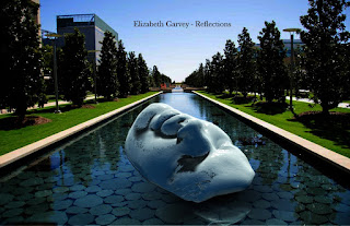
Concept: In my sculpture class we were making molds of our face using algenate and plaster. I figured it may be interesting to bring it into the digital space.

Scanning Process: I scanned the plaster cast from the side and top so the whole image showed. The different scans had to be merged, and then cleaned. Rapid works has many useful tools for filling holes.  Initially the scan had over one million polys so reducing it to 500k, 50k, and 5k made it more manageable. I ended up sticking with the 500k .Some of the geometry was missing large pieces so using bridges, and filling holes was necessary. After that the rhino IGES file was necessary to ensure there were no naked edges, before bringing into Keyshot Renderer.

Rendering Process: So in Keyshot I had to match the lighting to the background image. This included matching the perspective using perspective match as well as the environment lighting for the final composition. I decided to give the object a material that resembles stone, because I figured  it would look like an interesting contrast to the water. finally I composited the render passes in Photoshop.

Sunday, December 10, 2017

Scott Choi: Week 13 - Laser Scanning

Scanned object
RapidWorks screenshots
Ghosted, no naked edges
Render 1
Render 2
Concept:
For this assignment, I decided to scan an alien head with headphones made out of clay. I made this back in middle school for art class, and my parents kept it. I liked it back in the day, and it seemed like a fun object to scan.


Scanning Process/Technique:
I used the NextEngine scanner to scan my object. The scanning process was pretty straightforward once I got a working scanner. I did a 360 scan and decided I didn't need a top and bottom scan since my object hardly had any surfaces there. I trimmed out any unwanted objects and sent my file into RapidWorks. Instead of fusing my model, I decided to manually fill all the holes because it yielded a cleaner result. I used the bridge and fill gulf tool a lot. Afterwards, I smoothed my model using the Sandpaper and Smooth All tools. Then, I used the Simplify tool to set the poly-face count to 200k for my hi-poly version and 1.5k for my low-poly version. To create my nurbs version, I used the Simplify - Auto Surfacing tool. I set it to create an Evenly Distributed Network surface on my object. I imported my file into Rhino to check for naked edges. To create the final render, I took my model into Keyshot. 

Rendering Process/Materials:
For my first render, the backdrop image I chose was the inside of the Bio-engineering Science Building. I thought having an interior shot with a floating alien head would be pretty funny. I set the backdrop image in Keyshot, and then matched up the perspective settings. After I placed my model where I wanted it, I applied a light blue Axalta material that gave it a glossy, metallic look. I played around with some of the environment and lighting settings to make sure my object blended into the backdrop nicely. The bounce light on the left/back side of my model matches the light from the left side, and the shadow and light on the top matches the light coming from the top. For the second render, I followed the same steps of matching the perspective and editing the lighting/shadow setup. However, I changed the environment light to 'Urban 4k' instead of using the 'Startup' lighting scene to better fit the outdoor location. I applied a metallic red paint material for this one, and it looks good. The reflective surface helps make it look more genuine, as the bounce lights make the model blend in. Another thing that helps is there is a ground and building reflection on the alien head, and the horizontal line on it matches with the horizontal line from the backdrop.