Sunday, February 5, 2017

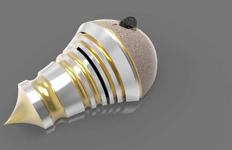
Darrius Williams: week 4 Mouse


Concept:
For my mouse model I based it on on crustaceans. specifically the trilobite and the horseshoe crab. i felt that the natural shape of those two creatures would lend well to a mouse design.I wanted this design to come off very symmetrical and circular. the shells of those animal also had many band like structures which is what i primarily focused on during the modeling.


Technique:
the techniques I used where pretty straight forward. i used curves to get the desired profile. Then I used the revolve tool to create the solid shape. I used a square curve to outline what i wanted to remove, then used the trim command to create a flat bottom. I used a elongate rectangle to inlay a hole for my mouse wheel and a ellipse to make the wheels scoop. 


Materials: 
My primary materials where metals such as brushed gold in the ring valley areas with a barely shiny steel finish for the mountain ridged areas. for the from head of the mouse i used a brown marble and more gold in the front semi-circle and the mouse wheel scoop. and for the mouse wheel itself I used black marble.

Jason Doze: Week 4 Hammer

Naked Edges


Explode/Layers 


Shot 1

Shot 2 

Reference 

 Concept: My concept here was to have a functional hammer and axe combination, not necessarily as a modern tool, but as a multi-use weaponized version of a hammer.  I wanted to give it a Celtic style but had some issues carrying out that vision so I tried to amend that with styling it in metal.  I also wanted this tool to look very clean, light, and potentially expensive.


Technique: I used boolean difference, extrude, mirror, alt-drag, and boolean union most to create the hammer.  I had some difficutlties with naked edges that I had to deal with after I made the sharp end of the them axe edge.  I was going to add some Celtic design and tried doing so with pipe and difference but for some reason I was unable to get the boolean difference to work for me and had to abandon the design altogether due to time constraints.


Materials:  I used scratched steel for the axe blade and hammer,  copper for the welds and brass for the connection of the hammer to the axe, as well as the handle.  I kept parts of the tool I thought would have less wear and tear polished to help achieve the high end look.  On the handle and the finger grooves I used a circular dot pattern that had almost a braided metal look, but after the rendering, it seemed to disappear.


Darrius Williams:Week 4 Hammer


Concept:
For my hammer design I wanted to merge a few concepts into one. I first though of what I wanted overall in a hammer's shape, for that I referenced war hammers, mostly those of viking age mostly because I'm a big metal fan and many bands in the genre reference vikings at one point or another which connected with my next reference. One of the bands that i listen to most and have seen the most is Ghost (B.C.) so I took some cues in my original design from their "square hammer" in their new single as well as a call out to the instrumentalists of the band "the nameless Ghouls" by using their alchemy symbols in the hammer head.


Technique:

to build my hammer I started by using curves to get the shape i wanted for the ends. I wanted the hammer to be symmetrical,very blocky looking from the end view but curvy in its profile. so the base curve shape is reminiscent of a dog collar pendent( dog bone shaped). Then I used the sweep 2 to bridge the to curves into a solid. then I used a similar technique we employed during the light saber model to make my handle. for detail and to finish rounded and chamfered the hammer ends and the handle its self as well as Boolean difference some alchemy symbols I made with curves into both sides of the hammer.


Materials. the hammer itself is comprised of to materials. Metal and wood, the metal was a blue anadized steel that I added a crack texture to the bump made to give it some age. the wood is a grey-brown like wood that I choose because it had the appearance of being waterlogged and old to go alone with the cracked metal of the hammer head.


Anisha Chaudhary: Week 04 Hammer


Concept:
For my hammer model, I imagined a fighter from a video game using a long hammer as a spear. I looked up references of hammers that are used in Anime and found many female fighters that would use a long hammer, usually slung behind their shoulders with some decoration that represents the character at the end of it. I liked the idea of making the hammer appear heavy, and I also like that it looks like a mixture of a claw hammer and a sledgehammer.

Modeling Techniques:
I blocked out the main pieces and separated them in Maya. I started with the hammer head as a rectangular prism and created a smaller cube for the claw and elongated it. I changed the vertices at the claw to make it appear smaller as it gradually went further from the hammer head. I merged the claw with the head and I used a bend deform to make the hammer have a bend as it went down to the claw. This is the main reason I did the blocking out in Maya because I wasn't sure how to create that effect of a bent claw in Rhino. I then created the top piece and handle using a cylinder and resizing it's bottom vertices, and then added a sphere and a two cylinders for the bottom piece as decoration. I then took my model into Rhino. I had some trouble with this at first. It was an issue with my model being a closed mesh instead of a closed poly surface, but this was solved by typing in the command "Mesh to Nurbs". I then made the opening of the claw by creating a curve, revolving it, then using the command "Boolean2Objects". I went back and filleted the entire hammer. I think the mistake I made was blocking this object out in Maya, because there are many obvious faces showing in the cylinders for the handle and bottom decoration.

Materials:
The materials I chose were chosen so that it looked like a Knight's weapon. I chose Brass Rough for the handle piece and the end piece as decoration. I chose black walnut as my wood for the pole to make it look old fashioned and used. I chose Anodized Silver as the metal for my hammer's head. I thought this silver made the hammer appear very heavy.


Ashley D Goodenough: "Lyretail" Prosthetic Accessory

Concept:
My focus for Digital Fabrication this semester is the study, design, and fabrication of various prosthetic accessories for specific uses. My first project, which is for a below-knee accessory, will be a prosthetic accessory for scuba diving. I’m calling it Lyretail (or alternately, Scalefin), because my main inspiration for the form comes from a family of gorgeous saltwater fish called Lyretails, also sometimes known as Scalefins. It’s also a fun play on words, and I’ve become endeared to it. There are many variations of the lyretail, but they all have exaggerated and slightly asymmetrical tail fins, and their coloring tends to be dramatic. My goal for this design is to make a diving prosthetic that echoes the streamlined and elegant forms of oceanic fish. The flipper will be similar to a split-fin in that the paddle will not be a solid piece - it will be for diving in conditions where the tide is less strong and unpredictable and you want a little more fine control of your movement. The lower leg portion of my concept draws from the shape of the wings of a manta ray.

From my research, I’ve gathered that a single-axis foot is what most people want from a scuba prosthetic - this way, the foot/fin only moves in one plane and has a predictable path of motion. Another need is ease of attachment and detachment of the flipper to the prosthetic foot, which in most cases is a Sach foot. Given the limited availability of dive prosthetics out there, it’s fair to say that another desire is more customization of the shell to suit your personal style. With these main ideas, I started concepting the Lyretail. When the model is finished, I plan on the ankle joint being a single-axis of my own design. It will ideally be able to lock in 2 or 3 positions, using some sort of manual dial. Additionally, the flipper will either be modeled in a way that means it can be easily slid onto a foot underwater and tightened around the heel, or it will be modeled so that if it were printed in a flexible and water-safe material, it would be simple to slip on the Sach foot and over the heel. The top leg portion will be completely separate from the flipper, but will be connected to the joint and the Sach foot design that fits into the flipper. 
In addition to my online research of scuba prosthetics out there currently, I also interviewed a family friend who is a recent amputee and a dive master. We met and talked about how his dive prosthetic works, and how I could go about making my final design effective but still appealing. He agreed with the need for a single-axis rotation in the ankle, and liked the idea of a locking mechanism - he’s actually been designing something similar recently for his own use, since he’s an engineer by trade - and the need for the flipper to be easy and fast to put on and adjust. I learned that I either need to create a leg design that is a completely functional underwater prosthetic that can use a vacuum and pressurization to stay attached, or my design must be purely a surrounding shell that can fit around an existing prosthetic. I haven’t decided which direction I’m going to go with that yet. He emphasized as well something I need to generally keep in mind in this business: every single prosthetic or prosthetic accessory is designed for a particular person, because everyone’s situation is going to be a little different - height, weight, amputation level, etc. I’m going to keep meeting with him when I have questions about ways to make my design more useful, or if I’m uncertain about my design interfering with its overall effectiveness.
Modeling (so far): 
My modeling deliverable at the end of the first four weeks of the semester was to have a clean, preliminary model of my prosthetic last; I would have the main form ready to go, and have very little detail. I got a little further than that, but may have to backpedal after talking with my friend and learning about how his personal diving leg works. I started scaling my concept drawings to each other in Photoshop and setting up some visual guides so that I could bring some orthographic views into Rhino and use them as a reference. I used PictureFrame to set up my front, side, and top views. I used Control Point Curves to first build the side silhouette of the leg and flipper together, then the front silhouette, creating only vertical curves for now. I also used my top view concept of the flipper to curve out the shape of the sole. Then, using Interpolate Points Curves, I drew horizontal curves to basically act as defining curves for the shape of the leg and flipper. I needed quite a few, since the flipper was more complex than a normal foot last would be. I used Rebuild to reduce the complexity of my curves, and made sure I still had intersection where I needed it. Using CurvatureGraph, I tested the continuity of my curves to make sure I was going to build a surface that was relatively smooth with curves that were continuous after I had been splitting and joining them. Before I used NetworkSrf to create my last, I split my vertical curves at the ankle, so that I could have separate surfaces for the leg and flipper, given that the leg could be a much simpler surface if I rebuilt it separately. Then, I selected all my curves and used NetworkSrf to build a loose surface. The flipper turned out to not be incredibly smooth, no matter how much I refined my curves (with RecordHistory turned on), so I turned on control points and sculpted it for a while just by manually moving points around (MoveUVN). I also used SetPt to align my loops to get a smoother surface, and Zebra to test my UV stretching. In the end, I also ended up using ExtractIsocurve to pull some new curves from the surface, and then rebuilt again using those slightly better shapes. Now that I had two surfaces, I could start refining. I used Interpolate Point Curves and Interpolate on Surface Curves to mirror my concept art from the side view, then projected my curves onto the surface. I used Trim to remove the parts of the surface I didn’t need anymore, but kept a copy of the original surface in case I paint myself into a corner later and need it back. Once the top of the flipper and the leg were trimmed, I used OffsetSrf (with Solid checked) on the leg to make it a closed polysurface with a width of a little over 1/8 inch. I FilletEdged every edge to almost the same radius. I attached the pole to the open leg design using some fancy cylinders and DupEdge to mimic my current shapes and a BooleanUnion/Boolean2Objects combination. For the flipper, I used my own foot last design to build an inner hole, then used BlendSrf to connect the two at the top. I used Patch to close up the bottom of the flipper, but had some cross sections to assist it in being smoother. Since that patch wasn’t quite lining up with my flipper and I needed to clothe my naked edges, I used JoinEdge to close the tiny gap.

Materials: Given that the model is not complete and separated into its component pieces yet, I'm holding off on deciding on materials. My favorite idea right now is to mimic the coloring and patterns of the batfish, and use a rubber-like material for the flipper and a hard plastic for the leg (the hard molded part of most prosthetic legs is made of carbon fiber):


References:
https://www.media.mit.edu/videos/ceb-2016-05-06/
http://biomech.media.mit.edu/#/

Brandon Wehenkel: Mouse


 Ghosted Black


Colored


Concept:  Logitec Trackball mouse.  The one I was using while creating it.  I've grown accustomed to a trackball mouse and feel that any other mouse is weird.  But I didn't want to use the tutorial because it wasn't precisely the shape I was looking for.  The real Logitech mouse is a lot more curved.


Keyshot 1


Modeling Techniques:
I used loft to make all 30 curves. Then I painstakingly spent 19 hours straight moving individual control points to make the shape it is in.  After the first 5 hours, I felt like I had made a huge mistake to design the mouse this way.  And I spent the rest of the time struggling with its wobbliness,  I know there has to be a better way to do it.  So it might be lumpy due to this fact.  I used my lofted curves to make the buttons by using projected curves and extrudeSrf.  I just created a sphere for the trackball.
Also because I had such a hard time making this design, I couldn't figure out how to do the buttons right.  I didn't really like how they looked merged into the object, but I did the two main buttons just to signify it were a mouse and didn't put the scroll wheel or the mouse button 3 and 4.  I had a hard time getting the curves to not merge into each other around the sphere. Due to the loft curves around the sphere not cooperating I wasn't able to make a fillet edge on the bottom of the mouse..  I initially had a curve that was meant to be the fillet, but I couldn't get it to work with the inset trackball.  I had already spent 19 hours. I probably would have needed to spend another 10 more hours just getting the fillet edge.
The sphere is not protruding through the object.  It is "hovering" inside the holder.  Hovering because thats the closest I could manage to simulating something clicking/fitting exactly inside its the spot.


Sphere Spot Detail


Keyshot 2


Materials:
Hard Black Plastic. Hard Black Plastic Shiney. Clear Shiney Blue Plastic, then changed the Diffuse Transmission: since I wanted to make the sphere clear it would have used the same color of the plastic underneath; that wasn't something I was going for.


Keyshot 3


Brandon Wehenkel: Hammer


Ghosted Black


Ghosted Colored


Concept:  I'm a gamer who doesn't play a whole lot of variety.  I play one or two different games over and over.  Where I got my inspiration was from two tools/weapons.
Thor's Hammer
Berzerker class battle axe from Tera
I liked both so I molded them together to make one very large hammer.


Keyshot 1


Modeling Techniques:
I started with the Tang by creating a Truncated cone, then on the ends put two Toruses with varing sizes.  Then I created a polyline and turned it into a pipe with rounded edges.  I caped the pipe with a truncated cone on each end.  Then I moved to the bottom of the handle and created 3 cones of various sizes and 4 pyramids.  Two of the pyramids I used bend to create curvature.

Then I dissected one of the curves for the hammer tutorial we had in class and turned it into a blade.  I did that by projecting curves and splitting the curve to a desired length.  I manipulated an outside curve slightly larger and then I connected them with my cutting polylines from earlier.  I joined the curves then extruded to create a sizable blade.  Then I used ChamferEdge on the exterior handle curve to 3.91245 to make the edge as close as possible to simulate a blade edge.  That ended up making a naked edge so I deleted the flat faces on the edges and capped the ends to fix whatever error that happend during the chamfering.

I created 9 more pyramids that simulate spikes for the hammer head and to give some functional decoration to the connecting pieces.  I used 3point rectangle to make the hammer head which I used filletEdge with a handle of 30 and then I chamferEdge to 15 for the outside faces.  I then fillet edged everything that I could with an edge of .05 or .02.

I then created a few pyramids and duplicated to a total of 63 and created a tenderizer on the hammer face.  Lastly I used the helix tool to make a decorative handle.  I made a pipe with the helix curve, duplicated it and used BooleanDifference to create the cut.  I liked it with the pipe still in so I can make it a different texture when I render it.


Keyshot 2


Materials:
Titanium Metal, Titanium Brushed Metal, Brass Scratched Metal then recolored it to look like Titanium,  Nickel Scratched Metal then added a red swatch. Mohogany Wood then changed the color to have a dark orange/brown color.


Keyshot 3

I didn't like the wood I had initially, so I used the wood planks material, changed the size of the texture, the color, and the direction.


Keyshot 4